For developers
Here we describe architecture of Microvolt code. If you want to stay as a user, all you need to know is user interface described in tutorial.
Microvolt supports multi-grid approach and possibility to deal with different types of meshes using the same interface. Basic operations such as analyzing device geometry, constructing Jacobian, performing Newton iteration, are implemented in a mesh independent way. Main "access object" of the model is class “container”, which is a template of mesh type. It can contain arbitrary number of meshes of this mesh type. Container manages interpolation and connection between different meshes. It also has information about boundary conditions which determine the role of mesh nodes lying outside the container boundary.
Class corresponding to particular mesh type (“mesh” later on) defines a set of update points, memory layout and interpolation. It must implement the following functionality: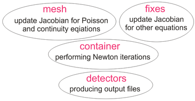
- define a "control region" where mesh stores and interpolate variables;
- return an interpolation for any variable at arbitrary location inside control region, binding mesh memory array indices and coefficients;
- define an iterator of all nodes composing the mesh;
- provide optimized procedure to construct Jacobian for Poisson and continuity equations.
Various kinds of meshes can be designed to conform to this model. Currently we use only rectangular mesh with finite difference discretization of Poisson and continuity equations. Step along each direction of rectangular mesh can be non-uniform.
Multiple meshes may be placed in the container. Each mesh should have a control regions and interpolation level. In case the meshes intersect, the actual variable update is performed in the mesh of higher level, while the lower level mesh uses interpolation given by higher level mesh.
Microvolt-based application has five computation stages which are implemented in the most general way and do not depend on the mesh construction details:
- Geometry setup. At this stage user specify calculated volume, meshes, material properties and geometry of the structure, boundary conditions, generation profile and set of points ("detectors") where calculated variables are recorded to output text files.
- Organizing meshes memory layout. At this stage container analyzes nodes collection returned by each mesh. It tests each node position, if it is (1) inside container, (2) outside container but borders with some internal node, (3) outside container and doesn’t border with any internal node (these nodes will not be stored by mesh), (4) inside container but belongs to region of higher level mesh (values at these nodes will be interpolated by other mesh). Mesh memory layout is organized basing on the obtained information concerning mesh nodes position.
- Analyzing geometry. At this stage container analyzes mesh nodes position relatively to specified media and boundaries. This information is used to assign coefficients values in discretized equations.
- Main loop which consists in applying Newton iterations until converged solution will be found.
Poisson and continuity equations constitute main bulk equations. Any mesh must be capable of updating Jacobian for these bulk equations on a specified range of nodes. For this purpose mesh should have some specialized algorithm that takes its memory layout into account.
Jacobian updates for all other types of equations (for example, boundary conditions) are organized in mesh independent way given by “fix” classes. Note that unlike the traditional approach of including the specialized updates into the main update loop and testing each time the equation type flags, these updates are performed as separate fix loops. Unlike the basic update, the fixes are implemented in a general mesh-independent way.
- Recording output data to text files which can be read or plotted by some graphical program (f. e. gnuplot). User specifies points where he wants to store variables putting “detectors” there. Detectors do not correspond to real objects in space. We just use term “detector” to denote points where values will be stored.
Detectors are implemented in the more general way independent from meshes and physical model (we use same detectors in EMTL to store electromagnetic fields).
Fourth and fifth simulation stages are repeating for each simulated voltage value.
Access to Microvolt architecture is provided via user interface implemented in class “Experiment”. Being a user, you just call functions of Experiment without knowing about other Microvolt classes which are actually doing the whole job.